
NEWS > Technical Knowledge Hub > A Step-by-Step Guide to Inverter Installation
A Step-by-Step Guide to Inverter Installation
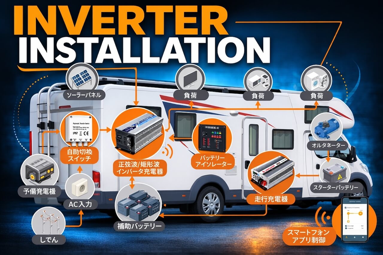
Power Inverter Installation Guide
Installing a power inverter allows DC battery power to operate standard AC appliances. Proper installation is essential for safety, performance, and long-term reliability.
This guide outlines the general best practices for installing DC-AC power inverters in applications such as recreational vehicles (RV), marine vessels, off-grid cabins, mobile service vehicles, and residential backup systems.
LinkChamp designs inverter solutions for these environments as a professional Taiwan inverter manufacturer.
Planning the Installation
Before installing an inverter, it is important to evaluate several system factors:
- Battery system voltage
- Maximum inverter power
- DC cable size
- Ventilation and mounting location
- Grounding and safety protection
Proper planning prevents common problems such as voltage drop, overheating, and inverter shutdown.
Step 1 – Selecting the Installation Location
The inverter location plays an important role in system reliability.
Ventilation
Power inverters generate heat during operation. Install the inverter in a location that allows sufficient airflow around the unit.
Recommended clearance:
| Location | Minimum Clearance |
|---|---|
| Side clearance | 5 – 10 cm |
| Rear clearance | 5 – 10 cm |
| Front ventilation | unobstructed |
Blocked airflow may cause the inverter to shut down due to over-temperature protection.
Distance from Battery
DC cable length should be kept as short as possible to reduce voltage loss.
Typical recommended DC cable length:
| Inverter Size | Recommended Cable Length |
|---|---|
| <1000W | < 1.5 m |
| 1000–2000W | < 1.2 m |
| >2000W | < 1 m |
However, the inverter must not be installed inside the same sealed compartment as lead-acid batteries because hydrogen gas may accumulate during charging.
Environment
Install the inverter in a location that is:
- dry
- cool
- well ventilated
- free from dust or oil
- away from flammable materials
Avoid direct sunlight or areas exposed to water.
Step 2 – DC Cable Selection
DC current increases significantly at lower voltages, making proper cable sizing critical.
Approximate current requirements can be estimated using:
DC Current = Inverter Power ÷ Battery Voltage
Example:
| Inverter Power | 12V System | 24V System |
|---|---|---|
| 1000W | ~83A | ~42A |
| 1500W | ~125A | ~63A |
| 2000W | ~167A | ~83A |
Because of these high currents, thick copper cables are required to safely carry the current and minimize voltage drop.
Typical recommended cable sizes:
| Inverter Power | 12V Cable | 24V Cable |
|---|---|---|
| 1000W | 22 mm² | 14 mm² |
| 1500W | 38 mm² | 22 mm² |
| 2000W | 50 mm² | 38 mm² |
| 3000W | 50 mm² | 38 mm² |
In practice, cable quality and conductor material are just as important as cable size. Poor-quality cables can cause excessive voltage drop, overheating, or unstable inverter operation.
To ensure safe installation, LinkChamp inverters are supplied with high-quality copper DC cables that are properly matched to the inverter's power rating according to LinkChamp's internal cable specification standards. These cables are designed to support the expected current load while maintaining safe operating temperatures.
For most installations, using the original cables supplied with the inverter is recommended to ensure compatibility and optimal performance.
Step 3 – Battery Connection
Most inverters include two DC terminals:
- Positive (+) terminal
- Negative (–) terminal
Connection order:
- Connect the positive cable (red) from the inverter to the battery positive terminal.
- Connect the negative cable (black) from the inverter to the battery negative terminal.
⚠ Important: Never reverse the polarity. Reversed DC connections may damage the inverter.
Even though LinkChamp inverters include fuse protection to help prevent further internal damage from incorrect connections, reversed DC connections should be avoided by all means.
Step 4 – DC Fuse or Circuit Breaker
A DC fuse or circuit breaker should always be installed on the positive DC cable.
Recommended fuse placement:
- Within 30–45 cm (12–18 inches) of the battery terminal.
Typical fuse sizing:
| Inverter Power | Recommended Fuse |
|---|---|
| 1000W | 150A |
| 1500W | 200A |
| 2000W | 250A |
The fuse protects the wiring and battery system in case of short circuits.
Step 5 – Chassis Grounding
Proper grounding is essential for electrical safety.
Most inverters include a chassis ground terminal that must be connected to a grounding point.
Grounding locations depend on installation type:
| Installation Type | Ground Connection |
|---|---|
| Vehicle | vehicle chassis |
| Boat | marine grounding system |
| Fixed installation | earth grounding rod |
Grounding ensures that electrical faults are safely discharged and helps reduce electrical noise.
Step 6 – Connecting AC Loads
Once the DC wiring is complete, AC appliances can be connected to the inverter output.
Typical supported loads include:
- laptops
- televisions
- refrigerators
- power tools
- lighting systems
LinkChamp pure sine wave inverters provide stable AC output suitable for sensitive electronics.
Always ensure the total load does not exceed the inverter's continuous power rating.
Example inverter ratings from the SN series include 1000W, 1500W, 2000W, and 3000W continuous output with higher surge capability.
Step 7 – First Power-On Procedure
When powering the inverter for the first time, follow this sequence:
- Ensure DC cables are securely connected.
- Turn ON the inverter first.
- Then turn ON the connected appliances.
Turning on appliances before the inverter may cause an initial surge load that triggers overload protection.
Step 8 – Operating Considerations
Energy-Saving Mode
Some inverters include a power-saving mode that periodically checks for AC load. This can introduce a short startup delay of several seconds when appliances are turned on. LinkChamp's pure sine wave SN-Series and modified sine wave ES-Series have energy-saving mode that efficiently reduce the standby energy consumption.
Continuous High Load Operation
Operating an inverter at full load for extended periods may increase internal temperature. If the inverter temperature rises too high, the system may trigger thermal protection shutdown.
Reducing the load improves long-term reliability.
Common Installation Mistakes
Avoid these common errors during installation:
| Mistake | Result |
|---|---|
| DC cables too long | voltage drop |
| undersized cables | overheating |
| no DC fuse | electrical hazard |
| poor ventilation | overheating shutdown |
| reversed polarity | inverter damage |
Following proper installation practices ensures safe and reliable operation.
Conclusion
Correct inverter installation ensures safe operation, high efficiency, and long equipment life. By carefully selecting the installation location, using proper DC cable sizes, installing appropriate fuses, and following grounding best practices, LinkChamp's inverter systems can operate reliably for many years.
LinkChamp manufactures high-quality pure sine wave inverters and inverter chargers designed for RV, marine, solar, and backup power systems worldwide.
Learn more about our company: About LinkChamp